48 DM01 Volt Mid Drive Motor Torque Sensor | Cadence Sensor
48 DM01 Volt Mid Drive Motor Torque Sensor | Cadence Sensor - black is backordered and will ship as soon as it is back in stock.
Couldn't load pickup availability
Description
TRANSFORM YOUR ORDINARY BIKE WITH OUR DM01 E-BIKE MID-DRIVE MOTOR!
POWER AND COMPATIBILITY
DM01 E-bike Mid-Drive Motor:
Equipped with Torque Sensor & Cadence Sensor.
Up to 1000W Rated Power Output.
Output Torque of 160Nm.
Compatible With 48, 52, 60 Volts Battery Range.
ENHANCED PERFORMANCE
Better heat dissipation ensures cooler and longer operation, optimizing E-bike motor efficiency.
Enhanced power output ranging from 750W to 1000W for dynamic e-bike performance.
High gear ratio (40.27) provides swift starts and impressive climbs.
Dual-clutch mechanism offers minimal resistance when pedaling E-bike mid-drive motors.
INTEGRATION AND DESIGN
Seamless integration with 95% of standard bike frames for easy installation of E-bike mid-drive motors.
Engineered for a smooth, comfortable journey, resembling the traditional bicycle feel.
Crafted from robust Aluminum alloys, ensuring durability in various environments.
Trusted by top electric bicycle manufacturers for enduring performance.
Elevate Your E-bike Journey Today !
Attention: To ensure optimal functioning and longevity, we highly recommend using the motor within the prescribed voltage range. Any unauthorized alterations beyond this range may void the warranty coverage.
Parameter
ADDITIONAL INFORMATIONS
| Mounting Position | Central |
|---|---|
| Shell Color | Black/Silver |
| Rated Power | 750W/1000W |
| Rated Voltage | 48V/52V |
| Reduction Gear Ratio | 40.27:1 |
| Max.Speed | 160rpm |
| Max Torque | 160N.m |
| Sensor Style |
Cadence/ Torque sensor |
| Teeth Species | 46T(or 34T/36T/ 38T/42T/52T) |
| BB Axle |
68mm~73mm ~100mm~110mm |
| Noise Level | <50dB |
| Work Temperature | -20℃ ~ 50℃ |
| Motor Weight | 5.8kg/6Kg |
| Waterproof Level | IP65 |
Specification
① BB=68-73DM01-1000DM01-750
| Component Part | Specification | Qty | BB=68 | BB=73 |
|---|---|---|---|---|
| Axle Screw | M8X1X15 | 2 | √ | √ |
| Left Crank | 170mm | 1 | √ | √ |
| Decoration Cap | 1 | √ | √ | |
| Non-standard Nut | M33.5X1.5 | 1 | √ | √ |
| Screw | See Column 4 or 5 | 2 | M6X14 | M6X20 |
| Reinforced Plates | 1 | √ | √ | |
| Drive Unit | DM01-1000 or DM01-750 | 1 | √ | √ |
| Crankset | 46T | 1 | √ | √ |
| Locknut | M42X1.5 | 1 | √ | √ |
| Right Crank | 170mm | 1 | √ | √ |
| Bushing | See Column 5 | 2 | × | Φ6X5 |
② BB=100-110DM01L-1000DM01L-750
| Component Part | Specification | Qty | BB=100 | BB=110 |
|---|---|---|---|---|
| Axle Screw | M8X1X15 | 2 | √ | √ |
| Left Crank | 170mm | 1 | √ | √ |
| Decoration Cap | 1 | √ | × | |
| Non-standard Nut | M33.5X1.5 | 1 | √ | √ |
| Screw | See Column 4 or 5 | 2 | M6X45 | M6X55 |
| Reinforced Plates | 1 | √ | √ | |
| Drive Unit | DM01L-1000 or DM01L-750 | 1 | √ | √ |
| Crankset | 46T | 1 | √ | √ |
| Locknut | M42X1.5 | 1 | √ | √ |
| Right Crank | 170mm | 1 | √ | √ |
| Lock Washer | See Column 5 | 2 | Φ6X32 | Φ6X42 |
Dimensions
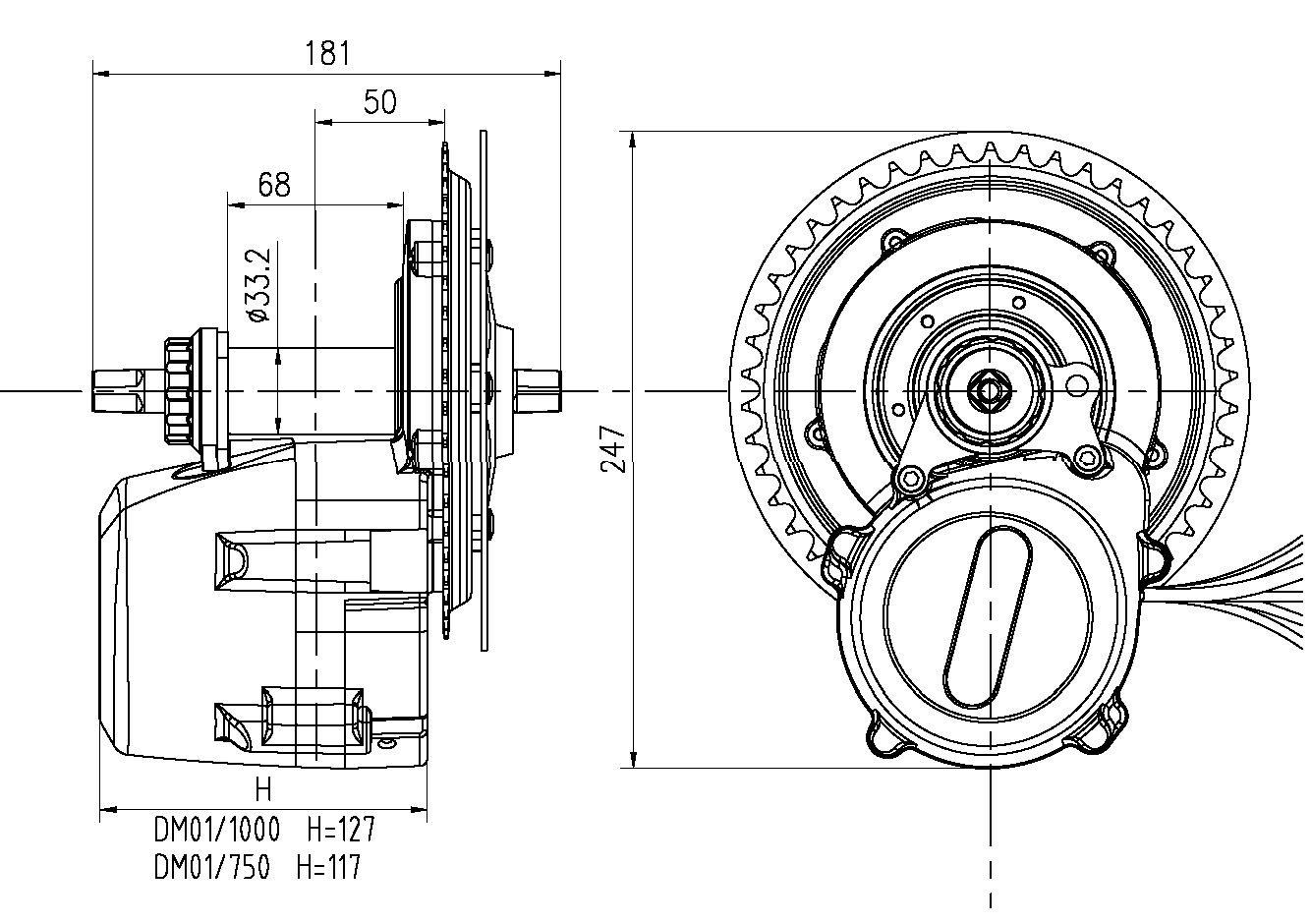
① BB=68   CL=50 (or 59)
         Model: DM01-1000     DM01-750


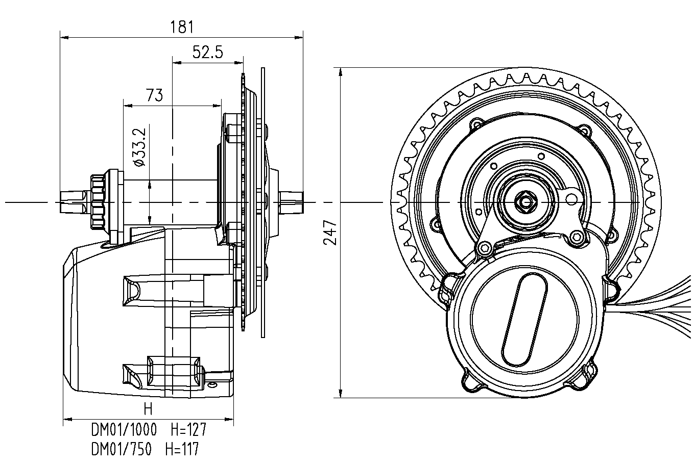
   ② BB=73   CL=52.5  (or 61.5)
         Model:   DM01-1000    DM01-750


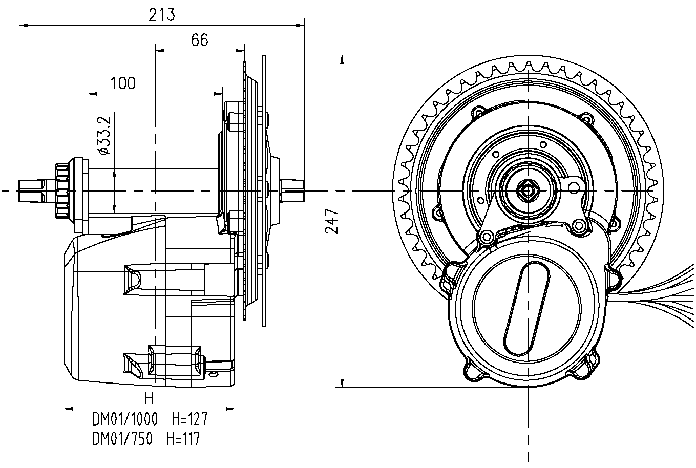
   ③ BB=100   CL=66 (or 75)
         Model:   DM01L-1000     DM01L-750


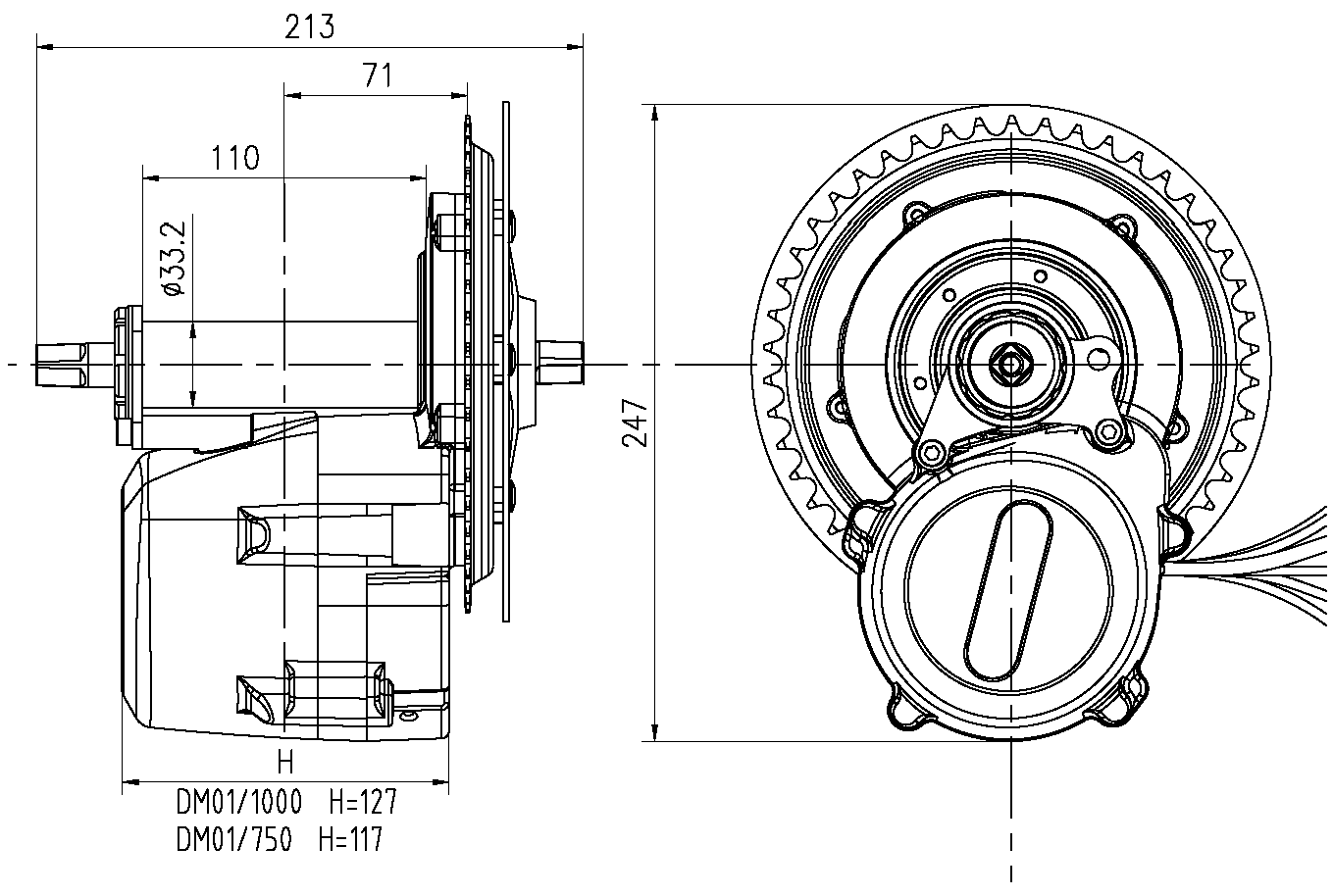
   ④ BB=110   CL=71 (or 80)
         Model:    DM01L-1000    DM01L-750

INSTALATION
1) Installation Tool

   ① Special wrench:


   ② General tools:  6mm  Allen wrench
                                            8mm  Allen wrench


2) Cranket Mounting
   -  Tools: Special wrench

   -  Operation: Align the internal splines of the cranket 8 with the external
      splines of the motor 7, press firmly to the end. Then tighten the lock nut  9,
      counterclockwise with a special wrench with a tightening torque of 15Nm

   -  Diagram:


3) Motor Mounting

  -  Insert the mid-drive motor through bottom bracket from right side of the bicycle
     frame and push it all the way


    -   Reinforcement Plate Mounting
    -   Tools: 6mm Allen Wrench
    -   Components(see: factory configuration):Reinforcement plate 6、M6 screw 5、
    washer or bushing 11
    -Requirement: Screw tightening torque 9-10Nm
    -Diagram:

    - BB=68


    - BB=73


    - BB=100~110


    ③  Non-standard nuts installation
    -Tools: Special wrench
    -Components(see: factory configuration):non-standard nut 4
    -Requirement: before tightening the nut, turn the motor clockwise until the
        motor is close to the lower tube of the frame and does not turn until it
        stops, then use a special wrench to tighten the nut, torque is 45-50Nm when
        tightening
    -Diagram:


    ④ Decoration cap installation
       - Components(see: factory configuration):decoration cap 3
       - Operation: turn the decoration cap clockwise to the end by hand
       - Diagram:


     ⑤  Crank Installation
        -Tool: 8mm Allen wrench
        -Components(see: factory configuration):axle screw 1、left crank 2、
                right crank 10
        -  Requirement: central axle screw locking torque is 35-40Nm
        -Diagram:


4) Speed Sensor Installation
   ①  Fasten the sensor to the frame flat fork with 2 cable ties, then install the
      magnets on the wheel spokes with a flat-blade screwdriver

      Notice:Make sure the magnetic field side of the magnet is aligned with the
      circular mark on the sensor

   ②  Loosen the screws on the sensor with a Phillips screwdriver, then move the
      receiver of the speed sensor, to ensure that the distance between the circular
      marking to the sensor surface and the magnet is from 2 to 10 mm, the tighten
      the screw with a screwdriver to complete the installation


      1-Sensor      2-Tie      3-Magnet    4-Screw   5-Receiver
 5) Wiring

    ① Operation:
      Insert the plugs on the bus cable, battery and speed sensor to the
      corresponding plugs of the motor,the other end of the bus cable can be plugged
      into the display, brake, throttle, etc.

    ② Precautions:
      Try not to pass all cables through the narrow space of the motor and bike
      frame, so as to avoid the cables being squeezed and damage

5. Warranty: The warranty on the motor is valid for 12 months from the SN date of
   production. This warranty does not mean that seller's products are not free from
   damage or permanent use.

6. Compatibility: Due to different communication protocols, our motors can only be
   used with the accompanying accessories we provide and are not compatible with
   accessories from other brands.

ATTENTION:   WARRANTY VOID IF SEAL IS REMOVED
Key product features
Can be highlighted here.
Description
Description
Description
TRANSFORM YOUR ORDINARY BIKE WITH OUR DM01 E-BIKE MID-DRIVE MOTOR!
POWER AND COMPATIBILITY
DM01 E-bike Mid-Drive Motor:
Equipped with Torque Sensor & Cadence Sensor.
Up to 1000W Rated Power Output.
Output Torque of 160Nm.
Compatible With 48, 52, 60 Volts Battery Range.
ENHANCED PERFORMANCE
Better heat dissipation ensures cooler and longer operation, optimizing E-bike motor efficiency.
Enhanced power output ranging from 750W to 1000W for dynamic e-bike performance.
High gear ratio (40.27) provides swift starts and impressive climbs.
Dual-clutch mechanism offers minimal resistance when pedaling E-bike mid-drive motors.
INTEGRATION AND DESIGN
Seamless integration with 95% of standard bike frames for easy installation of E-bike mid-drive motors.
Engineered for a smooth, comfortable journey, resembling the traditional bicycle feel.
Crafted from robust Aluminum alloys, ensuring durability in various environments.
Trusted by top electric bicycle manufacturers for enduring performance.
Elevate Your E-bike Journey Today !
Attention: To ensure optimal functioning and longevity, we highly recommend using the motor within the prescribed voltage range. Any unauthorized alterations beyond this range may void the warranty coverage.
Parameter
ADDITIONAL INFORMATIONS
| Mounting Position | Central |
|---|---|
| Shell Color | Black/Silver |
| Rated Power | 750W/1000W |
| Rated Voltage | 48V/52V |
| Reduction Gear Ratio | 40.27:1 |
| Max.Speed | 160rpm |
| Max Torque | 160N.m |
| Sensor Style |
Cadence/ Torque sensor |
| Teeth Species | 46T(or 34T/36T/ 38T/42T/52T) |
| BB Axle |
68mm~73mm ~100mm~110mm |
| Noise Level | <50dB |
| Work Temperature | -20℃ ~ 50℃ |
| Motor Weight | 5.8kg/6Kg |
| Waterproof Level | IP65 |
Specification
① BB=68-73DM01-1000DM01-750
| Component Part | Specification | Qty | BB=68 | BB=73 |
|---|---|---|---|---|
| Axle Screw | M8X1X15 | 2 | √ | √ |
| Left Crank | 170mm | 1 | √ | √ |
| Decoration Cap | 1 | √ | √ | |
| Non-standard Nut | M33.5X1.5 | 1 | √ | √ |
| Screw | See Column 4 or 5 | 2 | M6X14 | M6X20 |
| Reinforced Plates | 1 | √ | √ | |
| Drive Unit | DM01-1000 or DM01-750 | 1 | √ | √ |
| Crankset | 46T | 1 | √ | √ |
| Locknut | M42X1.5 | 1 | √ | √ |
| Right Crank | 170mm | 1 | √ | √ |
| Bushing | See Column 5 | 2 | × | Φ6X5 |
② BB=100-110DM01L-1000DM01L-750
| Component Part | Specification | Qty | BB=100 | BB=110 |
|---|---|---|---|---|
| Axle Screw | M8X1X15 | 2 | √ | √ |
| Left Crank | 170mm | 1 | √ | √ |
| Decoration Cap | 1 | √ | × | |
| Non-standard Nut | M33.5X1.5 | 1 | √ | √ |
| Screw | See Column 4 or 5 | 2 | M6X45 | M6X55 |
| Reinforced Plates | 1 | √ | √ | |
| Drive Unit | DM01L-1000 or DM01L-750 | 1 | √ | √ |
| Crankset | 46T | 1 | √ | √ |
| Locknut | M42X1.5 | 1 | √ | √ |
| Right Crank | 170mm | 1 | √ | √ |
| Lock Washer | See Column 5 | 2 | Φ6X32 | Φ6X42 |
Dimensions
① BB=68   CL=50 (or 59)
         Model: DM01-1000     DM01-750


   ② BB=73   CL=52.5  (or 61.5)
         Model:   DM01-1000    DM01-750


   ③ BB=100   CL=66 (or 75)
         Model:   DM01L-1000     DM01L-750


   ④ BB=110   CL=71 (or 80)
         Model:    DM01L-1000    DM01L-750

INSTALATION
1) Installation Tool

   ① Special wrench:


   ② General tools:  6mm  Allen wrench
                                            8mm  Allen wrench


2) Cranket Mounting
   -  Tools: Special wrench

   -  Operation: Align the internal splines of the cranket 8 with the external
      splines of the motor 7, press firmly to the end. Then tighten the lock nut  9,
      counterclockwise with a special wrench with a tightening torque of 15Nm

   -  Diagram:


3) Motor Mounting

  -  Insert the mid-drive motor through bottom bracket from right side of the bicycle
     frame and push it all the way


    -   Reinforcement Plate Mounting
    -   Tools: 6mm Allen Wrench
    -   Components(see: factory configuration):Reinforcement plate 6、M6 screw 5、
    washer or bushing 11
    -Requirement: Screw tightening torque 9-10Nm
    -Diagram:

    - BB=68


    - BB=73


    - BB=100~110


    ③  Non-standard nuts installation
    -Tools: Special wrench
    -Components(see: factory configuration):non-standard nut 4
    -Requirement: before tightening the nut, turn the motor clockwise until the
        motor is close to the lower tube of the frame and does not turn until it
        stops, then use a special wrench to tighten the nut, torque is 45-50Nm when
        tightening
    -Diagram:


    ④ Decoration cap installation
       - Components(see: factory configuration):decoration cap 3
       - Operation: turn the decoration cap clockwise to the end by hand
       - Diagram:


     ⑤  Crank Installation
        -Tool: 8mm Allen wrench
        -Components(see: factory configuration):axle screw 1、left crank 2、
                right crank 10
        -  Requirement: central axle screw locking torque is 35-40Nm
        -Diagram:


4) Speed Sensor Installation
   ①  Fasten the sensor to the frame flat fork with 2 cable ties, then install the
      magnets on the wheel spokes with a flat-blade screwdriver

      Notice:Make sure the magnetic field side of the magnet is aligned with the
      circular mark on the sensor

   ②  Loosen the screws on the sensor with a Phillips screwdriver, then move the
      receiver of the speed sensor, to ensure that the distance between the circular
      marking to the sensor surface and the magnet is from 2 to 10 mm, the tighten
      the screw with a screwdriver to complete the installation


      1-Sensor      2-Tie      3-Magnet    4-Screw   5-Receiver
 5) Wiring

    ① Operation:
      Insert the plugs on the bus cable, battery and speed sensor to the
      corresponding plugs of the motor,the other end of the bus cable can be plugged
      into the display, brake, throttle, etc.

    ② Precautions:
      Try not to pass all cables through the narrow space of the motor and bike
      frame, so as to avoid the cables being squeezed and damage

5. Warranty: The warranty on the motor is valid for 12 months from the SN date of
   production. This warranty does not mean that seller's products are not free from
   damage or permanent use.

6. Compatibility: Due to different communication protocols, our motors can only be
   used with the accompanying accessories we provide and are not compatible with
   accessories from other brands.

ATTENTION:   WARRANTY VOID IF SEAL IS REMOVED
Reviews (0)
Reviews (0)
Highlight title
Text to highlight a key feature of your product
Highlight title
Text to highlight a key feature of your product


